
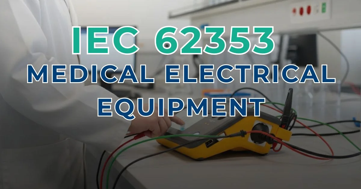
A nurse calls: “The monitor is behaving oddly — can we still use it on the next patient?” In that moment, you don’t need theory. You need a repeatable, documented process that helps you determine whether the device can be safely returned to clinical use.
That is exactly where IEC 62353 medical electrical equipment testing becomes relevant. IEC 62353 provides a practical framework for in-service electrical safety verification, particularly for recurrent testing and testing after repair. Unlike IEC 60601-1, which primarily addresses safety and essential performance requirements associated with the design and evaluation of medical electrical equipment, IEC 62353 is intended for testing equipment during its operational life.
In this essential guide 2026, you’ll learn how electrical safety testing medical equipment is approached under IEC 62353 / IEC EN 62353: how to identify the equipment protection class and applied parts, how to structure the test sequence, how direct, differential and alternative leakage-current methods differ, and what information should be documented to produce clear and traceable results.
You’ll also see why the correct test method and evaluation criteria depend on the equipment configuration rather than on a single universal limit, and how classification, measurement method and documentation work together within an IEC 62353 testing workflow.
If you need the verification performed professionally rather than carrying it out in-house, you can request our IEC 62353 electrical safety test service in Spain, including documented measurements and a technical report for each tested device.
What IEC 62353 covers (and what it doesn’t)
In-service testing vs design type testing (IEC 62353 vs IEC 60601-1)
If you searched “IEC 62353 medical electrical equipment”, you are probably looking for a practical way to assess electrical safety during the operational life of medical equipment, rather than information about product design and conformity assessment.
That distinction is fundamental. IEC 60601-1 establishes general requirements for the basic safety and essential performance of medical electrical equipment and is primarily applied within the design, manufacturing and conformity-assessment context. IEC 62353, by contrast, provides methods intended for testing medical electrical equipment during its service life, including recurrent testing and testing after repair.
Key takeaway: IEC 62353 provides a structured framework for assessing the electrical safety of medical electrical equipment in service. It does not replace the design and conformity requirements of IEC 60601-1.
When to apply IEC 62353: before use, periodic tests, after repair
A practical way to understand IEC 62353 medical electrical equipment testing is to think of it as electrical safety assessment at specific points during the equipment life cycle.
Typical situations include:
- Before putting equipment into service, where an electrical safety assessment is required as part of the technical acceptance or commissioning process.
- During recurrent or scheduled testing, according to the maintenance strategy, manufacturer instructions and procedures established by the healthcare organization.
- After repair or servicing, particularly when the intervention may have affected protective earth, insulation, the mains circuit, power supply or other safety-related components.
The exact scope of testing should always reflect the equipment design, the intervention performed, the manufacturer’s instructions and the applicable technical procedure.
How “allowable values” relate to IEC 60601-1 editions
One of the most common mistakes in electrical safety testing medical equipment is treating pass/fail limits as universal numbers that can be applied to every device.
Under IEC 62353 / IEC EN 62353, the evaluation depends on factors such as the equipment protection class, the type of applied parts, the measurement being performed and the selected leakage-current method.
This is why the test result should never be interpreted as an isolated number. A technically useful record should identify the device configuration and measurement method before comparing the measured value with the applicable allowable value.
Manufacturer instructions also remain important, particularly where the manufacturer specifies particular test procedures, test intervals or acceptance criteria for the equipment.
Practical implication: in electrical safety testing medical equipment, the correct sequence is to identify the equipment first, select the applicable test method, perform the measurement and then evaluate the result against the appropriate criteria.
Equipment classification you must identify first
Before performing electrical safety testing medical equipment, first identify how the device is classified. In an IEC 62353 medical electrical equipment workflow, this determines which measurements are applicable, how the device should be connected to the analyzer, which leakage-current methods can be used, and how the results should be interpreted.
Three characteristics are particularly important: protection class, applied-part type, and whether you are testing individual ME equipment or an ME system.
Protection class: Class I vs Class II (what changes in testing)
Start with the equipment protection class, because it determines how protection against electric shock is achieved.
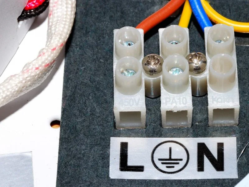
- Class I equipment uses basic insulation together with a protective earth (PE) connection as part of its protection strategy. Where applicable, protective earth resistance should therefore be verified before proceeding to leakage-current measurements.
- Class II equipment relies on double or reinforced insulation and does not depend on protective earth as a means of protection. Protective earth resistance is therefore not applicable, and the test configuration must be selected according to the equipment design and the measurements required.
- Internally powered equipment may require a different test configuration depending on whether it can also be connected to mains power, external power supplies, accessories or applied parts during normal operation.
The important point is that IEC 62353 testing is not a fixed sequence applied identically to every device. The test setup must reflect the electrical protection concept of the equipment being evaluated.
Applied parts: Type B / BF / CF (why limits differ)
Next, identify whether the equipment incorporates applied parts and how they are classified. An applied part is a part of the medical electrical equipment intended to come into physical contact with the patient for the equipment to perform its intended function.
The main classifications are:
- Type B: provides the level of protection associated with Type B applied parts and is not intended for direct cardiac application.
- Type BF (Body Floating): provides a higher degree of protection against electric shock and incorporates a floating applied part.
- Type CF (Cardiac Floating): provides the highest degree of protection among these classifications and is suitable for applications involving direct cardiac connection.
In IEC EN 62353 testing, applied-part classification influences the test configuration, the measurements that may be required and the allowable values used when evaluating patient-related leakage currents.
For equipment with several patient leads or accessories, the test configuration should also clearly identify which applied parts were connected and evaluated.
ME equipment vs ME system (practical implications)
Finally, determine whether you are evaluating individual ME equipment or an ME system.
- ME equipment: an individual item of medical electrical equipment.
- ME system: a specified combination of items of equipment, at least one of which is ME equipment, interconnected by a functional connection or through a multiple socket-outlet arrangement.
This distinction matters because the configuration being tested can affect both the measurement setup and the documentation required.
For an ME system, the technical record should clearly identify:
- Which equipment and accessories were included.
- How the components were interconnected.
- The protection class and applied parts involved.
- The measurement method and test configuration used.
- Any relevant conditions that could influence the results.
The IEC 62353 medical electrical equipment test record should therefore describe not only the measured values but also the configuration in which those values were obtained.
Once protection class, applied-part type and equipment/system configuration have been identified, the applicable IEC 62353 measurements can be selected and interpreted with substantially greater technical clarity.
IEC 62353 test sequence (Annex workflow)
When people search IEC 62353 medical electrical equipment, they are often looking for a practical and repeatable testing sequence. The important point is that IEC 62353 does not mean applying exactly the same measurements to every device: the sequence and tests must reflect the equipment protection class, applied parts, configuration and applicable manufacturer instructions.
A practical workflow begins with inspection and identification, continues with the electrical measurements that apply to the device, and finishes with functional verification and a documented technical evaluation.
Step 1 — Visual inspection (most failures start here)
Every electrical safety testing medical equipment workflow should begin with a visual inspection.
Check the condition of the mains cord, plug, enclosure, strain relief, connectors, accessories, applied parts and any other element that could affect electrical or functional safety. Look for damage, contamination, fluid ingress, loose parts, modifications or signs of overheating.
If the inspection identifies a condition that could make energizing the equipment unsafe, the electrical test should not simply continue as if the visual inspection had passed. The finding should be documented and evaluated before proceeding.
Step 2 — Protective earth resistance (when applicable)
For Class I equipment, the protective earth connection forms part of the protection against electric shock. Where accessible conductive parts are connected to protective earth, the continuity and resistance of that path should therefore be evaluated as part of the IEC 62353 workflow.
This measurement is not applicable in the same way to Class II equipment, which does not rely on protective earth as a means of protection.
Performing the protective earth assessment before the relevant leakage-current measurements also helps confirm that the equipment configuration is suitable for the subsequent tests.
Step 3 — Insulation resistance (when appropriate)
Insulation resistance can provide useful information about the condition of insulation barriers, but it should only be performed where it is appropriate for the equipment and test configuration.
Under IEC 62353 / IEC EN 62353, the applicability of insulation resistance testing should be considered together with the equipment design, manufacturer instructions and sensitivity of the electronics involved.
It should therefore not be treated as a mandatory identical measurement for every item of medical electrical equipment.
Step 4 — Leakage current tests (equipment + applied parts)
Leakage-current testing is one of the central elements of IEC 62353 medical electrical equipment verification.
IEC 62353 provides different measurement methods, including direct, differential and alternative methods. The appropriate method must be selected according to the equipment configuration and the measurement being performed.
Depending on the device, testing may include:
- Equipment leakage current, evaluated according to the applicable equipment configuration and method.
- Applied part leakage current, where the equipment incorporates patient applied parts for which this measurement is applicable.
This is why the previous classification step is essential. Protection class, applied-part type B, BF or CF, power configuration and selected measurement method all influence how the test is performed and how the result is evaluated.
Step 5 — Functional checks and final evaluation
Electrical measurements alone do not provide the complete picture. After the applicable safety tests have been completed, the equipment should also undergo the functional checks appropriate to the device and the intervention performed.
The final technical record should clearly document:
- The tests performed.
- The measurement method used.
- The measured values.
- The equipment configuration.
- Any observations or anomalies.
- The final evaluation and any corrective action required.
This final step turns individual measurements into a traceable IEC 62353 technical evaluation that can be associated with the equipment history and reviewed during future maintenance or technical investigations.
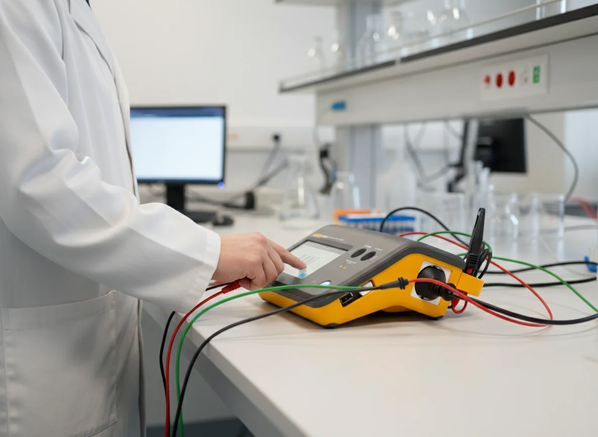
Leakage current methods explained: direct, differential and alternative
Leakage-current testing is one of the most important parts of IEC 62353 medical electrical equipment verification. Under IEC 62353 / IEC EN 62353, different measurement methods may be used depending on the equipment design, protection class, test configuration and measurement being performed.
The three principal approaches are the direct method, differential method and alternative method. They should not be treated as interchangeable shortcuts: each method has specific conditions of use and limitations that must be considered before interpreting the result.
Alternative method: when it can be appropriate
The alternative method uses a defined test configuration to evaluate leakage without operating the equipment in exactly the same way as during a direct mains-powered leakage measurement.
It can be useful for recurrent electrical safety testing medical equipment, but its applicability depends on the electrical design of the device. Equipment incorporating electronic mains switches, relays or circuits that are not fully connected unless the device is powered may require particular consideration because the alternative test configuration may not exercise every part of the mains circuit in the same way.
For this reason, the alternative method should be selected according to:
- The equipment design and protection class.
- The measurement required.
- The manufacturer’s instructions.
- The limitations of the test method and analyzer being used.
It should not automatically be considered the preferred method for every medical electrical device.
Direct method: what it measures and what to consider
The direct method measures leakage current through the measuring device while the equipment is energized under the specified test configuration.
Because the equipment is operating from the mains supply during this measurement, correct setup is particularly important.
For Class I equipment, where applicable, the protective earth connection should already have been assessed before proceeding with the relevant leakage-current tests.
When using the direct method, document:
- The equipment configuration.
- The measurement points.
- The operating condition of the device.
- The measurement method.
- The measured value and evaluation criterion.
The result should always be interpreted according to the equipment classification and applicable allowable value rather than as a universal pass/fail number.
Differential method: measuring current imbalance
The differential method determines leakage by measuring the difference between the current flowing through the live conductors supplying the equipment.
This approach can be practical because the device remains connected and operating while the analyzer evaluates the current imbalance.
However, the method must still be suitable for the equipment and electrical configuration being tested. Factors such as the supply arrangement, equipment load and analyzer capabilities can influence whether the differential method is appropriate.
As with the other methods, the resulting value must be interpreted within the IEC 62353 test configuration used.
Choosing the right leakage-current method
There is no single leakage-current method that should automatically be used for every IEC 62353 medical electrical equipment test.
Before selecting direct, differential or alternative measurement, identify:
- The equipment protection class.
- Whether applied parts are present and their classification.
- The equipment power configuration.
- The type of leakage current being evaluated.
- Any restrictions specified by the manufacturer.
- The capabilities and limitations of the electrical safety analyzer.
The selected method should then remain clearly associated with the measured result.
A technically useful record should identify at least the measurement method, test configuration, measuring equipment and measured value, together with the final evaluation.
Common pitfalls (and how to avoid them)
Some of the most common errors in electrical safety testing medical equipment come from the test setup rather than from the equipment itself.
Typical examples include:
- Skipping equipment classification before selecting the measurement method.
- Applying a method without considering its limitations for the device being tested.
- Failing to assess protective earth where applicable on Class I equipment.
- Using a universal leakage limit without considering the equipment and measurement configuration.
- Failing to record the method used, making future comparison of results difficult.
- Comparing measurements obtained with different methods without considering that the test conditions may not be equivalent.
The objective of IEC 62353 / IEC EN 62353 testing is therefore not simply to obtain a leakage-current value. The measurement must be linked to the equipment classification, selected method, test configuration and applicable evaluation criteria.
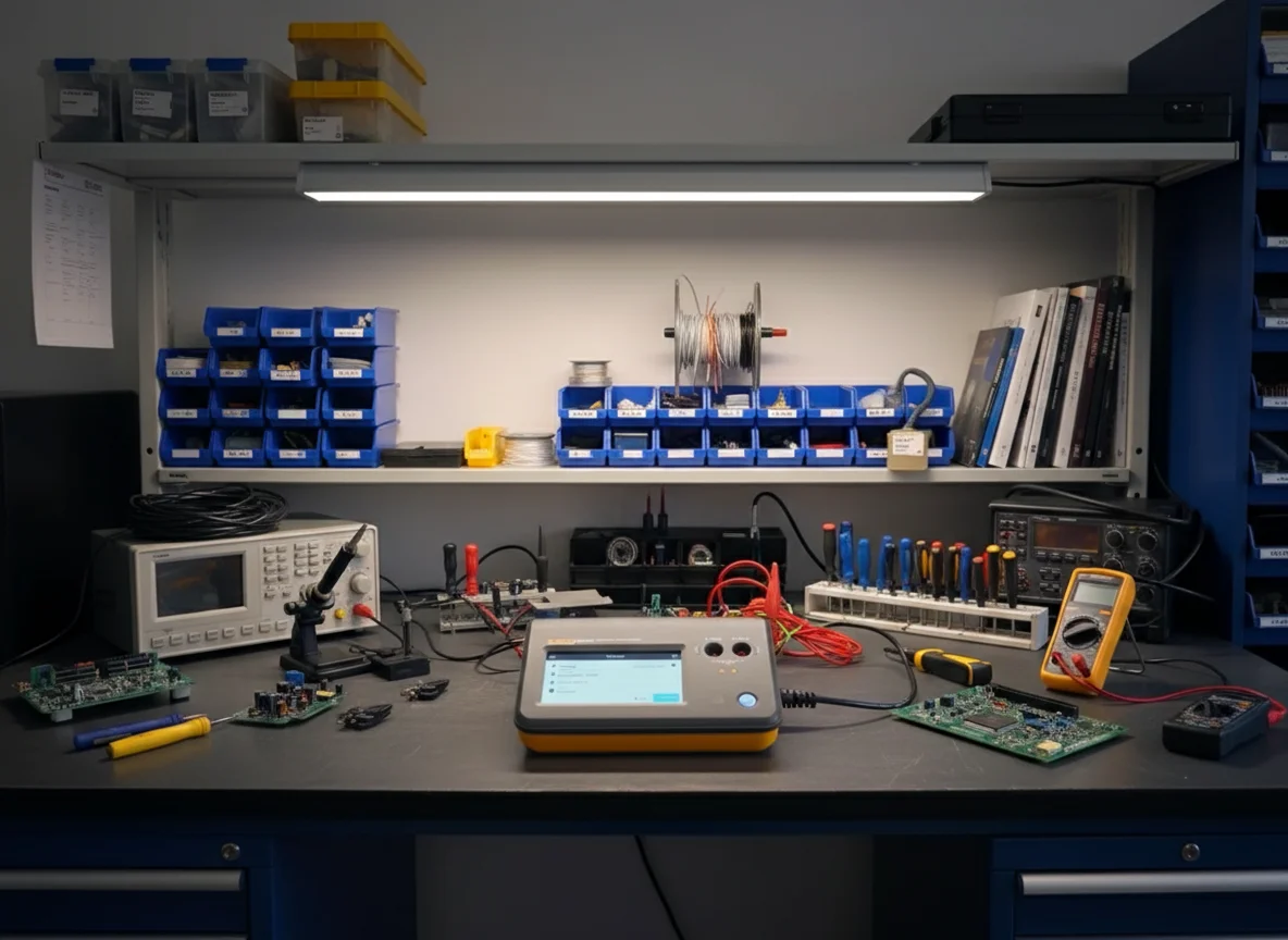
Allowable values and pass/fail criteria (without guessing numbers)
One of the most important principles in IEC 62353 medical electrical equipment testing is that allowable values should not be reduced to a single set of “universal limits” applied without context.
IEC 62353 contains tables of allowable values associated with different editions of IEC 60601-1. At the same time, the application of the measurement methods defined by IEC 62353 is independent of the IEC 60601-1 edition according to which the ME equipment or ME system was originally designed.
In practical terms, the correct approach is to identify the equipment and applicable test first, select the appropriate measurement method, perform the measurement under a defined configuration, and then evaluate the result against the relevant allowable value or acceptance criterion.
Why limits depend on class, applied part and method
The evaluation of an IEC 62353 measurement depends on both the characteristics of the equipment and the test being performed.
Relevant factors can include:
- Protection Class I or Class II, which determines whether protective earth forms part of the protection strategy and whether protective earth resistance testing is applicable.
- Applied part classification B, BF or CF, which affects the evaluation of patient-related leakage measurements.
- Direct, differential or alternative method, because the measurement configuration and resulting values are not necessarily equivalent between methods.
- Equipment or ME system configuration, including accessories and applied parts connected during the test.
- The particular measurement being evaluated, such as protective earth resistance, insulation resistance, equipment leakage or applied-part leakage.
A technically useful report should therefore never present only a measured number. It should associate that value with the equipment classification, measurement method, test configuration and applicable evaluation criterion.
Manufacturer instructions vs IEC 62353 allowable values
Manufacturer documentation remains an important part of the evaluation process.
Where the manufacturer specifies particular test procedures, intervals, configurations or acceptance criteria, those instructions should be considered when planning and evaluating the test. IEC 62353 also provides allowable values and testing requirements for recurrent testing and testing after repair.
A practical evaluation process should therefore consider:
- Manufacturer instructions and service documentation, where applicable.
- The relevant IEC 62353 test and allowable value for the equipment and measurement being performed.
- The measurement method used — direct, differential or alternative.
- The equipment configuration and applied parts present during testing.
- Any previous results or technical information that may be relevant when evaluating the current condition of the device.
This approach avoids one of the most common errors in electrical safety testing medical equipment: quoting a leakage-current or resistance limit without stating what was measured, how it was measured and to which equipment configuration the value applies.
Special cases: electronic switching, internal power sources and installations
Real medical equipment does not always fit a simple mains-powered test configuration. Some devices require additional consideration before selecting or interpreting an IEC 62353 measurement method.
Examples include:
- Equipment incorporating electronic mains switches, relays or switched-mode circuitry: some test configurations may not energize or include every relevant part of the mains circuit in the same way as normal operation. This must be considered when selecting the method.
- Equipment with internal power sources: the applicable measurements depend on how the device is powered during normal use and whether it can also be connected to mains power, external supplies or applied parts.
- Permanently installed equipment and ME systems: the installation, protective earth arrangement, interconnected equipment and supply configuration can affect both the test setup and interpretation of results.
- Equipment with multiple applied parts or accessories: the tested configuration should clearly identify which parts and accessories were included in the measurement.
The objective is not to force every device through an identical sequence, but to select an IEC 62353 / IEC EN 62353 test configuration that is technically appropriate for the equipment being evaluated.
Bottom line: in electrical safety testing medical equipment, a reliable pass/fail decision should connect four elements:
equipment classification → measurement method → applicable allowable value → documented result
That relationship is considerably more useful than publishing isolated numerical limits without the context required to interpret them correctly.
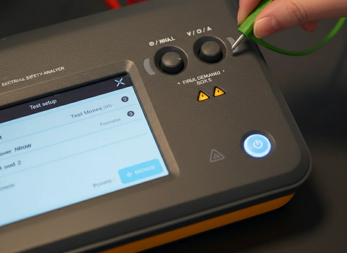
Documentation and reporting requirements (make it traceable)
In practice, IEC 62353 medical electrical equipment testing should not end with the measurement itself. The technical record must make it possible to understand what equipment was tested, which measurements were performed, how they were performed and how the final result was evaluated.
For this reason, electrical safety testing medical equipment is most useful when it follows a repeatable workflow and produces standardized records that can be associated with the equipment throughout its service life.
Information an IEC 62353 record should include
The exact content of the record may depend on the organization, equipment and procedure used, but a technically useful IEC 62353 record should normally identify:
- Testing organization or department responsible for the intervention.
- Technician or evaluator who performed the testing.
- Equipment identification, including device type, manufacturer, model, serial number and asset or inventory ID where available.
- Accessories and applied parts included in the tested configuration.
- Tests and measurements performed, including only those applicable to the equipment.
- Measured values and evaluation results for each applicable test.
- Measurement method used, particularly where direct, differential or alternative leakage-current methods are involved.
- Measuring equipment used, including its identification and calibration status where relevant.
- Date and reason for the test, such as recurrent testing or testing after repair.
- Observations, anomalies and corrective actions, where applicable.
- Final technical evaluation and identification or authorization of the evaluator according to the organization’s procedure.
The objective is simple: another qualified person should be able to review the record later and understand what was tested, how it was tested and why the equipment received its final evaluation.
Standardizing asset data (serial, inventory, accessories, test method)
Consistency in asset identification is essential for traceability.
If the same device appears under different names in different records — for example, “infusion pump”, “IV pump” or only a manufacturer name — it becomes more difficult to reconstruct its history, compare previous measurements or identify recurrent failures.
For an IEC EN 62353 testing program, it is useful to standardize fields such as:
- Device category.
- Manufacturer and model.
- Serial number.
- Asset or inventory ID.
- Protection class: Class I or Class II.
- Applied-part classification: B, BF or CF, where applicable.
- Accessories included in the tested configuration.
- Leakage-current method used: direct, differential or alternative.
- Reason for testing: recurrent test, after repair or other documented technical intervention.
This transforms individual measurements into a traceable equipment history rather than a collection of isolated readings.
Recommended IEC 62353 report structure
A standardized report can make results easier to review and compare between interventions. A practical structure is:
1. Administrative information
- Testing organization or department.
- Technician or evaluator.
- Date and location.
- Reason for testing.
2. Equipment identification
- Device type.
- Manufacturer and model.
- Serial number and asset ID.
- Protection class.
- Applied-part classification, where applicable.
- Accessories included in the test.
3. Test configuration
- Referenced procedure or standard: IEC 62353 / IEC EN 62353.
- Applicable measurement method or methods.
- Measuring equipment used.
- Calibration status of the test instrument where relevant.
- Relevant information about the installation or test configuration.
4. Results
- Visual inspection and observations.
- Protective earth resistance, where applicable.
- Insulation resistance, where applicable.
- Equipment leakage current and measurement method, where applicable.
- Applied-part leakage current and measurement method, where applicable.
- Functional checks appropriate to the equipment.
- Measured values and evaluation for each test performed.
5. Final evaluation
- Overall technical result.
- Observations or limitations.
- Corrective actions required, where applicable.
- Requirement for repair or retesting where necessary.
- Identification or authorization of the evaluator according to the applicable procedure.
A report structured in this way links the measured values to the equipment configuration, measurement method and final technical decision, which is essential for meaningful IEC 62353 traceability.
Digital recordkeeping and traceability
Digital recordkeeping is not the objective in itself, but it can considerably simplify the management of IEC 62353 medical electrical equipment results when the number of devices increases.
A structured digital system can make it easier to retrieve previous measurements, compare results over time, control recurrent testing, associate reports with individual assets and maintain a complete intervention history.
Whether records are managed through specialized software, a GMAO or another controlled system, the important requirement from an operational perspective is that the information remains identifiable, accessible, consistent and linked to the correct medical electrical equipment.
If your organization prefers to outsource the testing and receive documented results for each device, you can request an IEC 62353 verification report from Electromedicina Barcelona.
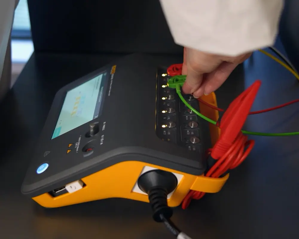
Test equipment: how the ESA715 electrical safety analyzer changes real workflows
Understanding IEC 62353 medical electrical equipment testing is only part of the challenge. In real maintenance environments, the workflow must also be repeatable, efficient and properly documented.
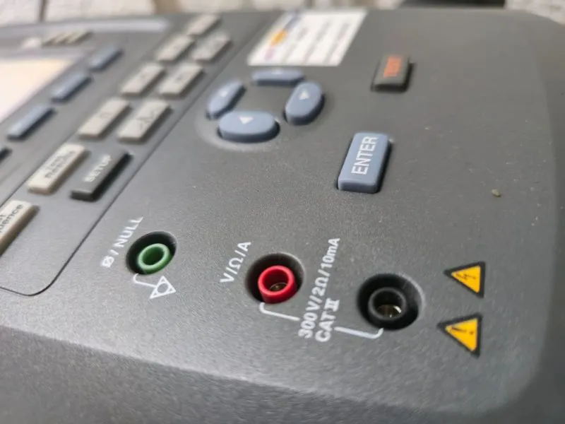
An electrical safety analyzer can help standardize electrical safety testing medical equipment by guiding technicians through measurements, associating results with individual assets and reducing manual transcription between the test instrument and the final technical record.
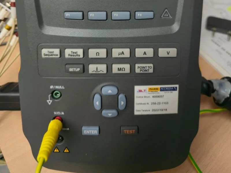
The ESA715 electrical safety analyzer is particularly relevant in this context because it combines electrical safety measurements with guided workflows and integration with Fluke Biomedical’s OneQA software.
What an electrical safety analyzer should support (standards + workflows)
For recurrent IEC 62353 / IEC EN 62353 testing, the analyzer should support more than individual electrical measurements.
Useful capabilities include:
- Procedures or guided workflows that help technicians follow a consistent testing sequence.
- Support for the electrical measurements required by the applicable safety-testing procedure.
- Clear identification of the asset being tested.
- Recording of measurement methods and results.
- Storage and export of test data.
- Traceability between the device, procedure, measurements and final report.
The objective is not simply to automate testing. The analyzer should help maintain consistency while leaving the technician responsible for selecting the applicable tests, configuring the equipment correctly and evaluating the results.
ESA715 electrical safety analyzer: guided workflows and OneQA
The ESA715 electrical safety analyzer combines portable electrical safety testing with an interface designed for guided procedures and workflow automation.
Fluke Biomedical integrates OneQA workflow automation software with the ESA715. Procedures created in OneQA can be synchronized with the analyzer and executed directly on the device, while assets and completed results can be synchronized for later review and reporting.
From a practical maintenance perspective, this can help with:
- Standardizing test procedures between technicians.
- Running guided procedures directly from the analyzer.
- Associating results with specific medical equipment assets.
- Reducing manual transcription of measurement results.
- Exporting stored results for documentation or further processing.
- Printing completed results when required.
The current ESA700-series documentation confirms that results can be exported to a USB drive and printed using a compatible USB printer, while OneQA can synchronize procedures, assets and results.
The important point is that the ESA715 does not determine by itself which IEC 62353 measurement is appropriate or whether a medical device should pass or fail. The technician still needs to classify the equipment, select the applicable test method, confirm the test configuration and evaluate the measured values against the appropriate criteria.
In-house vs outsourcing: which approach makes sense?
Whether IEC 62353 medical electrical equipment testing should be performed internally or outsourced depends mainly on the size of the equipment inventory, available technical competence, test instrumentation and documentation requirements.
An in-house approach can make sense when the organization has trained personnel, suitable calibrated test equipment and a standardized procedure for classification, measurement, evaluation and recordkeeping.
Outsourcing may be more appropriate when testing volumes are occasional, internal instrumentation is unavailable, specialist support is required or the organization prefers to receive the measurements and technical documentation as part of the service.
A hybrid model is also possible: routine checks can be managed internally while particular repairs, complex equipment or specialized electrical safety verifications are supported by an external technical service.
For organizations in Spain that prefer to perform the testing internally but do not need to purchase dedicated instrumentation, electrical safety analyzer rental can also be an option.
Frequently Asked Questions about IEC 62353 medical electrical equipment
What is IEC 62353 used for in medical electrical equipment?
IEC 62353 medical electrical equipment is used for recurrent (periodic) testing and testing after repair to verify in-service electrical safety. It is designed for field/hospital workflows rather than design type-testing.
Can IEC 62353 replace IEC 60601-1 certification?
No. IEC 60601-1 is primarily a design/type-testing framework, while IEC 62353 is intended for in-service verification (recurrent tests and tests after repair). Use IEC 62353 to keep equipment safe during operation, not to claim design certification.
Which leakage-current method should I use: direct, differential, or alternative?
IEC 62353 describes three methods—direct, differential, and alternative—and the device under test should be evaluated to determine which method is applicable. That “method selection” must be documented to make results audit-ready
Why does IEC 62353 mention “allowable values” and IEC 60601-1 editions?
IEC 62353 contains tables with allowable values that relate to different editions of IEC 60601-1. Importantly, it states that the application of measuring methods is independent of the edition to which the device was designed so your report should always state the measurement method and configuration used.
Is “IEC EN 62353” the same as IEC 62353?
In Europe you’ll often see IEC EN 62353 (or national adoptions). For example, the Spanish adoption UNE-EN 62353 corresponds to EN 62353:2014, which adopts IEC 62353:2014.
What must be included in an IEC 62353 test report?
At minimum, documentation should clearly identify who performed the test, which device/accessories were tested, which tests and methods were used, measured values, and the final evaluation (pass/fail) so the record is traceable and audit-ready.
I need a report-ready IEC 62353 verification can I outsource it?
Yes. If you prefer a report-ready verification instead of building an in-house workflow, you can request an IEC 62353 verification report (service page in Spanish)
Next steps: get a documented IEC 62353 verification report
IEC 62353 medical electrical equipment testing provides a structured approach to evaluating electrical safety during the operational life of medical equipment, particularly for recurrent testing and testing after repair.
A reliable electrical safety testing medical equipment program is not based on applying the same measurement or limit to every device. The test must reflect the equipment classification, applied parts, electrical configuration, measurement method and applicable evaluation criteria.
A consistent IEC 62353 workflow should therefore:
- Classify the equipment first, including protection Class I or Class II, applied parts B/BF/CF and the relevant equipment or ME system configuration.
- Perform the applicable test sequence, beginning with visual inspection and continuing with protective earth, insulation, leakage-current and functional checks where appropriate.
- Select and document the leakage-current method, whether direct, differential or alternative.
- Evaluate the measured values against the applicable criteria, considering IEC 62353 requirements and manufacturer instructions where relevant.
- Record the complete test configuration and results, including equipment identification, measuring instrument, measured values, observations and final technical evaluation.
The objective is not simply to generate a PASS or FAIL result. A useful IEC 62353 report should make it possible to understand what was tested, how it was tested, which values were obtained and how the final decision was reached.
If you need IEC 62353 verification for medical electrical equipment in Spain, send us the equipment type, manufacturer, model, number of units and location. We will review the scope and provide a clear technical proposal for the required testing and documentation.
![IEC 60601 2 4: requisitos para desfibriladores cardiacos [Guía esencial 2026]](https://electromedicinabarcelona.com/wp-content/uploads/2026/03/10-mm-1-400x250.webp)

![ISO 13485 que es y para qué sirve [Guía infalible 2026 para productos sanitarios]](https://electromedicinabarcelona.com/wp-content/uploads/2025/11/10-mm-59-400x250.webp)